Simulation in 5G Era: The Future is Now
The fifth generation of cellular wireless technology (5G) has been considered as a key enabler of a smart, digital, and connected society. As 5G technology has become increasingly important worldwide and will hugely support the next round of major industrial and economic revolution, accelerating 5G applications via simulation becomes the core engine for enterprises to be competitive.
5G possesses the traits of higher data rates, lower latency and greater bandwidth but it requires improvements in chip design and packaging, PCB design and antenna base stations. For engineering simulation, the 5G-specific massive multiple-input and multiple-output (MIMO) and beam steering bring ever-greater challenges in antenna arrays simulation. Chip design with higher performance and smaller size creates incredible challenges for signal integrity, power integrity, thermal management and product reliability. Moreover, in complex scenarios such as 5G-based autonomous vehicle, smart city, smart home, the connection between base stations and terminals and the interference between terminals make the simulation process even complicated.
e-works interviewed Shawn Carpenter, the Senior Product Manager for RF Products with Ansys. At present, Ansys capabilities have widely been used in the field of 5G, including chip design, packaging, RF, PCB, connectors, components, antennas and interaction design and analysis in complex scenarios. Through Ansys solution, AMD reduced the idle power by more than 70%, reducing the max TDP by 22% and improved the power-bandwidth slope by 400%. Paul Gilliland, Head of Business Development for PHAZR, commented that with the help of Ansys, PHAZR managed to save at least two weeks' time per design.
e-works:Compared with 4G technology, what are the specific application scenarios for 5G? What disruptive changes have been brought about?
Shawn: I think consumers of 5G technology are requiring the promise of:
5G provides great promise for applications we are familiar with today but will also enable technologies and opportunities that are still coming into focus. There are many areas where 5G will be disruptive, but here are a few examples where it has the potential to change life as we know it:
e-works: What challenges does 5G bring in product design and simulation for different product categories such as wireless equipment (mainly base stations), transmission equipment and terminal equipment in the industrial chain?
Shawn: Ansys provides engineering simulation physics software for multiple physics in the electronics, mechanical and fluids domains. In the 5G space, our tools have been heavily adopted for the design and analysis of ICs, packages, RF and PC boards, connectors, components, antennas and interaction with large environments. Although most of our simulation tools are used in these electronics domains, we also serve the tower and base station industries with analysis of structure integrity, cooling analysis and wind loading effects.
Our customers are innovating new base station and handset designs, as well as the large data centers which provide EDGE and cloud computing, to accommodate the considerable complexity added by 5G systems in the form of:
e-works: We know that Ansys has recently released the new version of 2020 R1. Could you talk about the new functions and innovations of Ansys 2020 R1 in 5G product design and simulation in terms of simulation capability and platform deployment?
Shawn: Ansys 2020 R1 has more new features than I could address here, but I will describe a few highlight features.
e-works: Antenna technology is one of the key fields of 5G technology, and the product design and precise modeling for antennas are crucial. From product components to system, and single physical domain to multi-physics, what new design and simulation technology do you think would be in need for antenna technology development with the arrival of 5G era? In particular, what changes have taken place in design and simulation of key technology fields such as large-scale MIMO and beamforming?
Shawn: Large-scale (massive) MIMO and beamforming are driving significantly higher computation loads for 5G communication systems—particularly for the base stations. 5G base stations (especially at mm-wave bands) will need to leverage beamforming to overcome the high propagation loss with antenna gain. Each subscriber will need their own radiation beam, which will need to follow them as they move through the coverage region. Base stations will need to continuously compute the channel state information (CSI) for each subscriber so that each beam can be updated quickly to ensure reliable service. This leads to much higher computation loads on the signal processing units that drive the beamforming. Further, beamforming for 5G will require more independent antenna channels, creating significant complexity for the RF Front-End design. With more devices comes the need to manage power and heat without resorting to active cooling systems. With more channels comes an impact on electronics reliability, and graceful degradation of performance must be engineered into the system so that downtime is minimized for maintenance. This drives several new needs for the antenna system design:
e-works: In the Ansys 2019 R3, there is a new 3D component finite array technology for solving the finite array antenna with non-identical unit cells. How does it achieve fast and accurate simulation of the complex array structure?
Shawn: 3D Component Finite Array Decomposition (3DC-DDM) was released to customers in Ansys 2019 R3 as an advanced beta feature and has now been fully released in Ansys 2020 R1.
3DC-DDM provides a faster, more efficient way to assess the performance of complete phased array systems than a full (explicit) phased array model, and provides full frequency sweeps for all ports, as well as composite radiation performance for the array under any beam steering condition.
3DC-DDM starts with the construction of one or more unit cells that comprise repeated parts of the array. It can accommodate:
The ability to create optimal meshes for each unique unit cell combined with the non-conformal mesh analysis provides incredible efficiency for this technique without loss of accuracy, and enables Ansys customers to solve much larger arrays on a typical workstation compared to modeling a full explicit array solution.
e-works: Since the antenna includes both circuit model and electromagnetic model, how does Ansys achieve co-simulation between field and circuit and accurately simulate the interaction of various components of elements?
Shawn: A powerful way to include the interaction between circuit components and field solution is through the use of HFSS 3D Components. 3D Components are “black box” elements with full field and port capability and are provided by many RF component vendors today. 3D Components can also be encrypted, so that when they are shared by vendors with customers, they are fully active for EM simulation, but the structure, mesh or fields cannot be observed inside the model. HFSS 2020 R1 comes with a large library of surface mount components and antennas from vendors like TDK, Coilcraft, Johanson, Mini-Circuits and from component specialists like Modelithics. In addition, many component vendors can create special 3D Component designs from HFSS and share with their customers in order to model integration into their designs with full EM interaction.
This will become even more important for 5G at higher frequencies where distributed element implementations will be fabricated into the packaging; Encrypted 3D Components provides a way for IP to be shared for advanced filters, splitters and circuits to be shared for detailed design integration.
e-works: At present, 5G network is mainly deployed in two different spectrums, sub-6GHz and mm-wave. What are the differences between sub 6GHz antennas and mm-wave antennas? What are their characteristics in engineering simulation respectively?
Shawn: Sub-6 GHz antennas typically have fewer antenna elements, and each element is comparatively large. MIMO is available in these antennas, but there are fewer beams and beam steering capabilities are not expected to be as advanced. Mm-wave 5G antennas, by contrast, will be composed of many more elements, each of which will be 5-10x smaller than their sub-6 GHz counterparts.
mm-wave antenna design will be much more challenging, for several reasons:
e-works: In addition to 5G antennas, complexity of 5G terminal products and network is also improved. For example, the chipset of a 5G mobile phone consists of RFIC, SoC, ASIC, cellular chip and mm-wave integrated circuit. What challenges do high performance and complexity of the chipsets bring to product design and simulation? And how does Ansys help enterprises cope with these challenges?
Shawn: There are a couple of significant challenges going on at the handset level:
e-works: Could you share some specific cases or application scenarios showing how Ansys accelerates the design and simulation of 5G antennas, SoC and mobile terminals, and help enterprises shorten the time to market. Does Ansys have specific data comparison in this respect?
Shawn: I mentioned earlier that testing a 5G handset for regulatory compliance is very costly—especially now that 5G phones are expected to have 2-4 separate mm-wave phased array antennas enabling many beam steering positions. Each beam position must be examined to ensure that the Power Density level requirement is not exceeded in order to be certified by relevant regulatory body. The US Federal Communications Commission (FCC) recently issued a new standard that allows simulation data of handsets to be used to identify a small number of beamforing settings that yield the highest PD values.
One large handset developer recently determined that full PD testing for their 5G handset at mm-wave bands would require nearly 6 months for all conditions. But using Ansys HFSS to identify a small number of worst cases for testing, they were able to accomplish their compliance certification testing within just a few days. This is a powerful advantage for handset developers who must meet aggressive product availability schedules.
e-works: The structure of 5G industrial chain is huge. What is the position of Ansys in the industrial chain? And how will Ansys build a 5G ecosystem together with partners?
Shawn: Ansys is in the business of high-fidelity physics simulation. Therefore, we are supporting the companies who are developing the hardware for handsets, base stations and computing infrastructure. We also support the customers developing front-haul and back-haul systems, as well as heating, cooling, power conditioning and installation structures. If engineering simulation based on the physics of electronics, fluids, thermal, mechanics and dynamics, etc. are required, Ansys seeks to provide an industry-leading solution.
Ansys partners with mechanical CAD (MCAD) and electrical CAD (ECAD) companies, where design concepts are typically drawn and managed for 3D and planar geometry. We ensure that designs developed within the project lifecycle management (PLM) environment can smoothly flow through the Ansys design, modeling and simulation workflow.
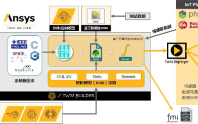
Finally, Ansys is partnering with companies like PTC and GE to provide Digital Twin and Digital Transformation, enabling customers to accurately assess performance of fielded hardware and consider in-place improvements to operating systems based on combining measurements with simulation.
e-works: China is promoting the construction of "new infrastructure", and 5G is considered to be one of the keys to "new infrastructure". From the perspective of Ansys, how do you view the development of 5G technology and market in China and globally?
Shawn: We recognize China as a major market for 5G innovation. In addition, China is one of the consumer markets that is most readily adopting 5G technology, with an enthusiastic and well-informed consumer base. 5G equipment manufacturers based in China are world leaders in the development of this technology. This is an important market to Ansys, and we are doing everything possible to meet the demands of design engineers in these companies to innovate and create the 5G products of tomorrow.
I think we can all agree that this is time of relative uncertainty in the 5G design and equipment markets. Ansys will continue to provide the tools that 5G innovators need across the globe in order to realize the promise of 5G that we have all been hearing about.
e-works: How do you view the trend of 5G technology development and its market in the future? What are your strategic objectives in promoting 5G technology?
Shawn: 5G technology development is trending toward electronics that package more speed and functionality in smaller, lower-power packages than ever before. Wireless connectivity is becoming central to much of the world’s economy and will provide the backbone for the next major industrial and economic revolution. We will see new electronics technology incorporated into the 5G ecosystem in the future in order to unlock more of the promise of high-speed, low-latency, high-capacity networking.
Some of these technologies may include:
He holds a BSEE from the University of Minnesota and a MSEE from Syracuse University, and has over 25 years of experience in applications, marketing and sales of high frequency electromagnetic and RF system analysis EDA software.
e-works interviewed Shawn Carpenter, the Senior Product Manager for RF Products with Ansys. At present, Ansys capabilities have widely been used in the field of 5G, including chip design, packaging, RF, PCB, connectors, components, antennas and interaction design and analysis in complex scenarios. Through Ansys solution, AMD reduced the idle power by more than 70%, reducing the max TDP by 22% and improved the power-bandwidth slope by 400%. Paul Gilliland, Head of Business Development for PHAZR, commented that with the help of Ansys, PHAZR managed to save at least two weeks' time per design.

e-works:Compared with 4G technology, what are the specific application scenarios for 5G? What disruptive changes have been brought about?
Shawn: I think consumers of 5G technology are requiring the promise of:
- Higher bandwidth (up to 1000x more data at 10x-100x faster rates)
- Lower network response latency (5x-10x faster)
- Vastly more connected devices (10x-100x more than today)
- Higher reliability in their networks (99.99% to 99.999% reliable)
5G provides great promise for applications we are familiar with today but will also enable technologies and opportunities that are still coming into focus. There are many areas where 5G will be disruptive, but here are a few examples where it has the potential to change life as we know it:
- Enabling autonomous vehicles for ride-share and delivery. In order to deliver safe autonomous transportation, significant AI is required both on the vehicle and in the Cloud. The vehicle will require very low-latency access to public safety systems in order to ensure safe passage through congested areas, especially when there are pedestrians and bicyclists.
- Virtual Reality and Augmented Reality. Certainly, we can imagine the impact of VR on the computer gaming industry. But imagine the impact of AR on things like class or laboratory instruction, medical education, mechanical servicing of complex devices like aircraft jet engines or computing center systems, and advanced industrial system monitoring and control.
- Remote Medical Treatment and Procedures. Imagine an expert surgeon in one city, performing a very sensitive life-saving procedure on a patient in a rural hospital, using remote-controlled robotic surgery. This has the potential to bring the best in medical care to every corner of the world.
- Advanced Industrial Control and Safety for Smart Factories. With hundreds or thousands of sensors and controls distributed throughout a smart factory, connected wirelessly to a central cloud management system, entire factories will be safer, more efficient, cleaner, require less labor, and more profitable to their operators.
- Entertainment and Education. We know that entertainment will be revolutionized by the ability to provide multiple very high-resolution video and audio streams to each consumer, but imagine the power of education that can bring to life nearly any subject with visually engaging graphics to illustrate complex concepts? With 5G, the bandwidth and AI will exist to give the student complete “hands-on” control for the education process.
e-works: What challenges does 5G bring in product design and simulation for different product categories such as wireless equipment (mainly base stations), transmission equipment and terminal equipment in the industrial chain?
Shawn: Ansys provides engineering simulation physics software for multiple physics in the electronics, mechanical and fluids domains. In the 5G space, our tools have been heavily adopted for the design and analysis of ICs, packages, RF and PC boards, connectors, components, antennas and interaction with large environments. Although most of our simulation tools are used in these electronics domains, we also serve the tower and base station industries with analysis of structure integrity, cooling analysis and wind loading effects.
Our customers are innovating new base station and handset designs, as well as the large data centers which provide EDGE and cloud computing, to accommodate the considerable complexity added by 5G systems in the form of:
- More frequency bands, including the addition of the 5G mid- and high-bands. All equipment serving 5G needs will be required to serve the new frequency bands
- Carrier Aggregation drives the need for more electronics in the RF front-end (RFFE), as well as the ability to combine transmission data streams across multiple frequency bands. This increases RFFE complexity a great deal.
- Massive MIMO and Beam Steering requirements for high-density base station array antennas. This creates significantly more complex base stations, with an order of magnitude more antenna elements.
- Mm-wave technology challenges. At mm-wave frequencies, every mm of tolerance matters. Electronic design of antennas and RF components must be designed with precision. With mm-wave technology comes the challenges of managing thermal issues with devices of lower power-added efficiency. To overcome the shorter wireless propagation range of mm-wave signals, base station and handheld antennas will need to utilize beamforming technologies to create directional radiation pattern gains, and the systems must be flexible enough to overcome human body interactions (for handheld devices) and serve many moving subscribers (for base station antennas).
- Dense packaging. Our customers need to pack more electronics onto each die, and within each package. They are using high-density interconnects such as interposers and embedded interconnects to combine chip and packaging media. This creates incredible challenges for signal integrity, power integrity, thermal management, electronics reliability and consistent RF performance.
- Power and thermal cost and reliability management of electronics for more access points, which may be located in areas that make maintenance service visits costly and difficult. Power is always a cost that must be managed by the provider, and adding more electronics generally runs counter to the cost.
- Compliance Testing and Certification of handheld devices has become a great deal more time-consuming and costly because of the addition of beamforming. Every possible radiating beam position must be evaluated to ensure that the device will meet regulatory and compliance requirements.
- New Technologies to expand performance. We are seeing customers explore new cutting-edge capabilities, such as QAM-512 and QAM-1024 waveforms, optical interconnects from chip-to-chip and module-to-module, and 3D ICs and packages. All of these technologies require careful consideration in the design phase to ensure signal integrity, power integrity, EMI, EMC, cost and performance requirements are met in order to support the full mission of a more powerful infrastructure with low-cost, low-power high-reliability systems and components.
e-works: We know that Ansys has recently released the new version of 2020 R1. Could you talk about the new functions and innovations of Ansys 2020 R1 in 5G product design and simulation in terms of simulation capability and platform deployment?
Shawn: Ansys 2020 R1 has more new features than I could address here, but I will describe a few highlight features.
- New 5G mm-wave Antenna Array Solver: 3D Component Domain Decomposition Method solver (Discussed more fully in #5, below. This was released as an advanced beta feature in Release 2019 R3, and is now fully released in 2020 R1.)
- Creeping Wave Physics for HFSS SBR+. HFSS SBR+ is a high-frequency electromagnetic solver that uses a Shooting and Bouncing Rays (SBR) technique to provide solutions for very electrically large problems. For instance, it can be used together with the HFSS finite-element method (FEM) solver to model the interaction between an antenna and its host vehicle, or with its surroundings. It is very efficient to model an HFSS FEM antenna model interaction with a car, ship, or even an entire city, providing wireless propagation modeling that accounts for multi-path, diffraction and absorption of microwave and mm-wave signals as they propagate through large environments. In 2020 R1, the HFSS SBR+ solver now features Creeping Wave physics for antennas that are integrated into platforms with curved bodies, capturing the effects of ground plane currents that roll off to the host that are not directly visible to the antenna. CW physics reproduces antenna radiation more accurately to non-line-of-sight regions for installed antennas on curved platforms.
- Power Density Calculation for 5G mm-Wave. New 5G antennas incorporated into handheld devices and onto base stations must meet new regulatory requirements at mm-wave that are based upon Power Density measurements. At mm-wave frequencies, fields penetrate less deeply into human tissue. HFSS 2020 R1 now includes automation for extracting and visualizing Power Density for any antenna or antenna array in order to test such devices virtually, saving months of time in compliance testing. Many 5G devices have used HFSS to perform this testing, as evidenced by filings on the US FCC device compliance database.
- Near-Field Magnetic Field and Poynting Vector Visualization and Export – for 5G power density calculation. Also related to Power Density calculation, a new capability for HFSS 2020 R1 includes the ability to visualize the Near Field Magnetic fields and Poynting Vector (radiation power vector) outside of computation domains. The fields can be computed and displayed in regions that do not require meshing and simulation, reducing simulation time and requirements for this information.
- Template projects and 3D Components for virtual EMI and EMC lab measurements. 5G devices are subjected to rigorous testing for electromagnetic interference (EMI) and electromagnetic compatibility (EMC). EMI and EMC testing is usually conducted in a test laboratory with special antennas and a special test chamber. In HFSS 2020 R1, template projects provide pre-created test chamber setups, ready for a customer to simulate a test by dropping their device model in for simulation. New 3D Components provide pre-made antenna and testing component models automatically to satisfy testing conditions.
- ECAD Xplorer for importing large GSDII mask files. Many customers in the integrated circuit (IC) application space need to evaluate dense interconnects, silicon interposers and other IC structures, and HFSS provides very accurate and efficient model extraction for these structures. In 2020 R1, we introduce a new IC design pre-processor called ECAD Xplorer, which streamlines the process of importing dense GDSII mask files, and automatically conditioning the geometries for fast, efficient EM simulation.
- 5G Radio Library RF systems for the EMIT RF Cosite Interference simulation. 5G radios must be evaluated for interference potential with other RF systems that exist in the same local environment, including public safety radios, unlicensed wireless networking systems, broadcast bands and business band radios. A new library of 5G radios has been added to the Ansys EMIT tools to analyze and mitigate RF cosite interference.
e-works: Antenna technology is one of the key fields of 5G technology, and the product design and precise modeling for antennas are crucial. From product components to system, and single physical domain to multi-physics, what new design and simulation technology do you think would be in need for antenna technology development with the arrival of 5G era? In particular, what changes have taken place in design and simulation of key technology fields such as large-scale MIMO and beamforming?
Shawn: Large-scale (massive) MIMO and beamforming are driving significantly higher computation loads for 5G communication systems—particularly for the base stations. 5G base stations (especially at mm-wave bands) will need to leverage beamforming to overcome the high propagation loss with antenna gain. Each subscriber will need their own radiation beam, which will need to follow them as they move through the coverage region. Base stations will need to continuously compute the channel state information (CSI) for each subscriber so that each beam can be updated quickly to ensure reliable service. This leads to much higher computation loads on the signal processing units that drive the beamforming. Further, beamforming for 5G will require more independent antenna channels, creating significant complexity for the RF Front-End design. With more devices comes the need to manage power and heat without resorting to active cooling systems. With more channels comes an impact on electronics reliability, and graceful degradation of performance must be engineered into the system so that downtime is minimized for maintenance. This drives several new needs for the antenna system design:
- RF FE design must be performed in a “thermal-aware” design flow. RF system performance must be guaranteed to work with passive cooling in extreme ambient environments. Thermal effects must be included with power amplifier and installed package design at each step of the process. Coupling to mechanical analysis is also needed, to ensure that connections and material stresses are within safe levels for IC, package and board integration, for solder connections and for all mechanical parts as they cycle through temperature fluctuations induced by both the outside environment and the electronic heating. Ansys HFSS couples electromagnetic analysis of ICs, packages and PCBs with Ansys Icepak to provide coupled thermal analysis. This solution also couples to the Ansys Mechanical suite to assess material stresses and find potential failures.
- High-fidelity array designs are needed for beamforming design and research. It is well known that the elements of an array can present very different loads to the power amplifiers and circuitry that drive them, and this in turn can provide errors to the beamforming. A high-fidelity model of the array is needed for system-level beamforming analysis, which includes the effects of the radome, the edges of the array plane, interruptions in the ground plane, mounting structures near the antenna, and even weather-induced effects like ice, water or dust on the radome. This behavior is needed at all frequencies, under all possible beam steering conditions. The Ansys 3D Component Domain Decomposition Method provides an array analysis solution to provide the needed solution at all frequencies, under all steering conditions within a single efficient solution.
- The MIMO beamsteering effects on the antenna element loading in an array induces stresses on the power amplifiers and LNAs to which they are attached. The amplifiers used in the designs must be designed to be robust with respect to all array conditions. Ansys provides circuit analysis tools to connect to electromagnetic designs for a complete circuit and EM analysis capability. In addition, Ansys has technical solution partners such as Amcad who provide specialized software tools for modeling in-place 5G mm-wave power amplifiers connected to Ansys HFSS phased array antenna models.
- MIMO and beam forming design will benefit greatly from matching the high-fidelity array model with the scattering expected in its installed environment. In the past, this required a test installation and significant time, equipment and personnel to perform over-the-air (OTA) testing. Ansys now provides the ability to connect an HFSS 3D Component Decomposition solution of the array with an HFSS SBR+ solution of a virtual city composed of accurate building structure and material definitions, and use simulation to compute the physical channel response and the optimal beamforming necessary to deliver the best signal to a subscriber. In this way, Ansys is enabling beamforming research to be conducted on a full size 5G base station array in a physics-accurate virtual environment. This is a powerful way to conduct OTA testing and research, without requiring a physical installation or city permits.
e-works: In the Ansys 2019 R3, there is a new 3D component finite array technology for solving the finite array antenna with non-identical unit cells. How does it achieve fast and accurate simulation of the complex array structure?
Shawn: 3D Component Finite Array Decomposition (3DC-DDM) was released to customers in Ansys 2019 R3 as an advanced beta feature and has now been fully released in Ansys 2020 R1.
3DC-DDM provides a faster, more efficient way to assess the performance of complete phased array systems than a full (explicit) phased array model, and provides full frequency sweeps for all ports, as well as composite radiation performance for the array under any beam steering condition.
3DC-DDM starts with the construction of one or more unit cells that comprise repeated parts of the array. It can accommodate:
- Multiple unit cell antenna cells;
- Edge effects;
- Radome structure over the elements, along the sides and in the corners of an array;
- Blank cells and “dummy” antenna elements;
- Transmission feed structures and polarizers embedded in layers beneath the antennas;
- Posts, ridges or other regular ground plane structures;
- Any structure embedded in the array in one or multiple unit cells of the antenna structure
- Mesh and solve each unit cell for an optimal mesh, and capture field behavior at the boundaries
- Using the radiation observed at the boundary of each cell in the fully defined array, solve for the composite radiation, near-fields and port characteristics.
The ability to create optimal meshes for each unique unit cell combined with the non-conformal mesh analysis provides incredible efficiency for this technique without loss of accuracy, and enables Ansys customers to solve much larger arrays on a typical workstation compared to modeling a full explicit array solution.
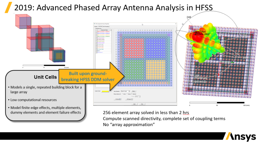
Ansys HFSS 3D Component Domain Decomposition enables efficient simulation of full 5G mm-wave arrays with radome and finite ground plane effects
(Full-size graphics available upon request)
e-works: Since the antenna includes both circuit model and electromagnetic model, how does Ansys achieve co-simulation between field and circuit and accurately simulate the interaction of various components of elements?
Shawn: A powerful way to include the interaction between circuit components and field solution is through the use of HFSS 3D Components. 3D Components are “black box” elements with full field and port capability and are provided by many RF component vendors today. 3D Components can also be encrypted, so that when they are shared by vendors with customers, they are fully active for EM simulation, but the structure, mesh or fields cannot be observed inside the model. HFSS 2020 R1 comes with a large library of surface mount components and antennas from vendors like TDK, Coilcraft, Johanson, Mini-Circuits and from component specialists like Modelithics. In addition, many component vendors can create special 3D Component designs from HFSS and share with their customers in order to model integration into their designs with full EM interaction.
This will become even more important for 5G at higher frequencies where distributed element implementations will be fabricated into the packaging; Encrypted 3D Components provides a way for IP to be shared for advanced filters, splitters and circuits to be shared for detailed design integration.
e-works: At present, 5G network is mainly deployed in two different spectrums, sub-6GHz and mm-wave. What are the differences between sub 6GHz antennas and mm-wave antennas? What are their characteristics in engineering simulation respectively?
Shawn: Sub-6 GHz antennas typically have fewer antenna elements, and each element is comparatively large. MIMO is available in these antennas, but there are fewer beams and beam steering capabilities are not expected to be as advanced. Mm-wave 5G antennas, by contrast, will be composed of many more elements, each of which will be 5-10x smaller than their sub-6 GHz counterparts.
mm-wave antenna design will be much more challenging, for several reasons:
- Antenna elements are much smaller, meaning that manufacturing tolerances will be more important to manage for reliable designs
- Many more elements will be needed. 5G mm-wave arrays appear to require on the order of 32 to 256 elements. This leads to complex feed network and amplifier chain designs that must fit into a smaller physical footprint. This drives challenges in antenna design, signal chain design, electronic packaging, signal integrity and power integrity.
- Thermal effects. More mm-wave amplifiers and LNAs in a tight space leads to heat, and the heat must be eliminated. RFFE design requires passive cooling and good heat sink design that extends all the way in to the ICs in order to ensure long-term reliability and expected operation in ambient environments from tropical to arctic. Power amplifier performance degrades with increased heating.
e-works: In addition to 5G antennas, complexity of 5G terminal products and network is also improved. For example, the chipset of a 5G mobile phone consists of RFIC, SoC, ASIC, cellular chip and mm-wave integrated circuit. What challenges do high performance and complexity of the chipsets bring to product design and simulation? And how does Ansys help enterprises cope with these challenges?
Shawn: There are a couple of significant challenges going on at the handset level:
- Need to incorporate deep submicron node silicon to add functionality, reduce power and size of the electronic footprint. ICs have an increased number of transistors, diving to smaller design node features (5 nm), and must exist in advanced packaging constructs to fit into the handset profile. Ansys SIwave provides simulation for SI and PI for dense planar MCMs and PCBs, and HFSS provides highly accurate simulation for interconnects and packages that are more 3D in nature.
- Need to incorporate multiple chip technologies for maximum efficiency. I think most handset developers agree that for mm-wave design, different IC processes are required for best power efficiency for the RF signal chain, and these are not the same processes as required for analog, digital or mixed-signal processing. This stresses the handset integration and packaging in order to combine best-in-class IC processes for the functions required. This requires careful design of the interconnection of these technologies that must serve very high data rates or RF frequencies. A highly accurate 3D field solution like HFSS or SIwave are needed for successful first-pass success.
- Need to identify potential signal integrity problems in increasingly complex IC layouts, which are increasingly becoming 3D stacked structures. Die-level crosstalk and coupling noise must be managed in dense IC designs. Ansys acquired Helic Software in 2019 to provide very accurate signal integrity analysis for 5G RFICs, silicon interposers, high-bandwidth memory (HBM) modules, and other stacked IC designs that are highly 3D in nature. Ansys provides the Helic RaptorX tool and workflow to provide SI and RF analysis for very large complex ICs with full process design kit (PDK) support from leading IC foundries.
- Need to carefully tune RF components such as inductors and transformers in the RF PA chip and signal chain chip sets. This year, Ansys has introduced RaptorH, which is streamlined to access complex IC technology through the RaptorX workflow, integrating the power of HFSS with major IC foundry PDKs. This gives RFIC designers the gold-standard accuracy of HFSS in an IC-centric design and analysis workflow.
e-works: Could you share some specific cases or application scenarios showing how Ansys accelerates the design and simulation of 5G antennas, SoC and mobile terminals, and help enterprises shorten the time to market. Does Ansys have specific data comparison in this respect?
Shawn: I mentioned earlier that testing a 5G handset for regulatory compliance is very costly—especially now that 5G phones are expected to have 2-4 separate mm-wave phased array antennas enabling many beam steering positions. Each beam position must be examined to ensure that the Power Density level requirement is not exceeded in order to be certified by relevant regulatory body. The US Federal Communications Commission (FCC) recently issued a new standard that allows simulation data of handsets to be used to identify a small number of beamforing settings that yield the highest PD values.
One large handset developer recently determined that full PD testing for their 5G handset at mm-wave bands would require nearly 6 months for all conditions. But using Ansys HFSS to identify a small number of worst cases for testing, they were able to accomplish their compliance certification testing within just a few days. This is a powerful advantage for handset developers who must meet aggressive product availability schedules.
e-works: The structure of 5G industrial chain is huge. What is the position of Ansys in the industrial chain? And how will Ansys build a 5G ecosystem together with partners?
Shawn: Ansys is in the business of high-fidelity physics simulation. Therefore, we are supporting the companies who are developing the hardware for handsets, base stations and computing infrastructure. We also support the customers developing front-haul and back-haul systems, as well as heating, cooling, power conditioning and installation structures. If engineering simulation based on the physics of electronics, fluids, thermal, mechanics and dynamics, etc. are required, Ansys seeks to provide an industry-leading solution.
Ansys partners with mechanical CAD (MCAD) and electrical CAD (ECAD) companies, where design concepts are typically drawn and managed for 3D and planar geometry. We ensure that designs developed within the project lifecycle management (PLM) environment can smoothly flow through the Ansys design, modeling and simulation workflow.
Finally, Ansys is partnering with companies like PTC and GE to provide Digital Twin and Digital Transformation, enabling customers to accurately assess performance of fielded hardware and consider in-place improvements to operating systems based on combining measurements with simulation.
e-works: China is promoting the construction of "new infrastructure", and 5G is considered to be one of the keys to "new infrastructure". From the perspective of Ansys, how do you view the development of 5G technology and market in China and globally?
Shawn: We recognize China as a major market for 5G innovation. In addition, China is one of the consumer markets that is most readily adopting 5G technology, with an enthusiastic and well-informed consumer base. 5G equipment manufacturers based in China are world leaders in the development of this technology. This is an important market to Ansys, and we are doing everything possible to meet the demands of design engineers in these companies to innovate and create the 5G products of tomorrow.
I think we can all agree that this is time of relative uncertainty in the 5G design and equipment markets. Ansys will continue to provide the tools that 5G innovators need across the globe in order to realize the promise of 5G that we have all been hearing about.
e-works: How do you view the trend of 5G technology development and its market in the future? What are your strategic objectives in promoting 5G technology?
Shawn: 5G technology development is trending toward electronics that package more speed and functionality in smaller, lower-power packages than ever before. Wireless connectivity is becoming central to much of the world’s economy and will provide the backbone for the next major industrial and economic revolution. We will see new electronics technology incorporated into the 5G ecosystem in the future in order to unlock more of the promise of high-speed, low-latency, high-capacity networking.
Some of these technologies may include:
- Photonic (optical) interconnects at the chip, package and module-level that will serve unprecedented data bandwidths, eliminating the bottlenecks formed by today’s metal interconnects. Ansys is anticipating this exciting future technology through our 2020 acquisition of Lumerical, a company that specializes in integrated optical designs in IC processes. We are excited about this new technology and believe it will completely change the art of the possible for IC data pipelining.
- Advanced materials and the process of material selection for consumer devices and infrastructure equipment. In 2019, Ansys also acquired Grant Materials—the world’s largest materials database providing material properties appropriate for analysis across all physics. This is a powerful tool for companies who wish to select materials for designs to match performance criteria balanced against cost and weight considerations.

He holds a BSEE from the University of Minnesota and a MSEE from Syracuse University, and has over 25 years of experience in applications, marketing and sales of high frequency electromagnetic and RF system analysis EDA software.