RADIOSS Application in Airbag Simulation
Abstract: Virtual modeling and simulation are increasingly used to help develop restraint systems, and airbag simulation is the necessary steps during airbag research and design progress. This paper introduces RADIOSS application in airbag simulation. The dynamic simulation has been checked with physical test and shows very good correlation, which proves that airbag modeling is reliable and acceptable.
Virtual modeling and simulation are increasingly used to help develop restraint systems and enhance the value of virtual design with simulation are regularly used by system supplier, which is effective in evaluating and optimizing the performance of restraint systems[1].
The most common airbag simulation method assumes uniform pressure and temperature everywhere inside the airbag. This is a close representative of the airbag after it is fully inflated and the gas flow inside airbag stabilizes. This paper uses uniform pressure method to achieve airbag validation.2 Theory
An airbag model in RADIOSS is defined as a monitor volume, the most important parts of airbag definition are gas properties of mass injection and outgoing mass, the latter often includes vent hole outgoing flow and porosity outgoing flow due to fabric material property.
2.1 Mass injection[3]
The amount of mass injected into the airbag needs to be defined with respect to time. The data can be obtained by airbag manufacturer or a tank experiment. A diagram of a classic tank experiment can be seen in Figure 1.
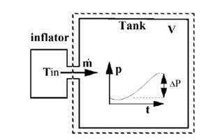
Figure 1. Tank Experiment Diagram
The mass versus time curve can be derived from the pressure curve if Tin is known:Where, M is the molecular weight of the injected gas, R is the perfect gas constant :
 .
.The average estimate for temperature of injection is:

Where P is the total pressure variation during the experiment. m is the total injected mass, which can be derived from the mass of propellant in the pyrotechnic inflator and the chemical reaction.
2.2 Outgoing mass determination[3]
2.2.1 Isenthalpic model
Venting or the expulsion of gas from the volume, the status is assumed to be isenthalpic. The flow is also assumed to be unshocked, coming from a large reservoir and through a small orifice with effective surface area.
Conservation of enthalpy leads to velocity u at the vent hole. The Bernouilli Equation is then written as:

Applying the adiabatic conditions:

Where P is the pressure of gas into the airbag, and ρ is the density of gas into the airbag.
Therefore, the exit velocity is given by:

Where
 is the averaged density of the gas and
 is the fraction of massic averages of heat capacities at constant pressure and constant volume.
The mass out flow rate is given by:

2.2.2 Chemkin model
Porosity definition can define the surface for outgoing flow with the following equation:

Where ρ is the density of the gas within the airbag, Funct_IDv is the outflow velocity function defined by users.
3 Airbag Definition
This section deals with airbags model implemented into RADIOSS code. There are several ways and methods to model an airbag with the “Monitored Volume” option, and uniform pressure classical method is commonly used, the keyword and brief description shown below.
Table 1 Type AIRBAG Keyword
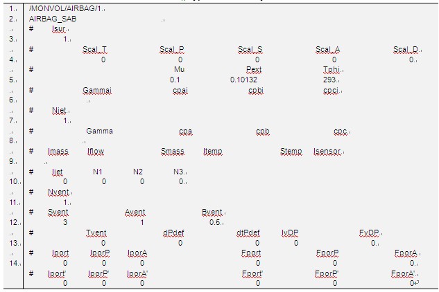
- Line 2:Isur defines airbag surface.
- Line 5, 6: Definition of initial gas properties inside airbag
- Line 7: Njet defines the number of injectors
- Line 8, 9: Definition of gas injection information, include gas properties, gas flow, temperature and sensor information, which is validated during Tank Test.
- Line 11: Number of Vent
- Line12-14: Definition of vent properties include vent area, out flow equation, scale coefficient, which are often validated by verification test. Outgoing mass determinations of Isenthalpic and Chemkin model have different definition.
FVMBAG type airbag of RADIOSS may be used for Out Of Position(OoP) situation where the gas flow effects must be taken into account.
4 RADIOSS Application
A specific series of airbag tests are conducted to help validate the modeling of side airbag, Drop tower test is commonly used to correlate airbag characteristics of airbag module in a controlled environment. The following is a successful example that simulated by RADIOSS, the set-up and acceleration result of impactor are shown in Figure 2, the acceleration data has similar output.
Figure 3 illustrates the kinematics comparison of the simulation with test result of the model, its kinematics sequency from the side view was captured corresponding to physical test view and the comparisons show very good correlation.
After airbag component validation, the airbag model can be applied in the airbag restraint system level simulation to evaluate the occupant performance.
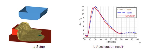
Figure 2. Setup and Acc result
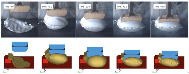
Figure 3. Kinematics Comparison of Simulation and Test Result
5 Conclusion
The CAE-based airbag simulation is presented in this paper with drop tower test. Both acceleration result and kinematics comparison show that the validated airbag definition is reasonable and accepted.
Uniform pressure method of RADIOSS is a quick method and gives rather good results for predicting the interaction of airbag with surrounding objects at the stages of deployment especially in fully inflated status.
Acknowledgment
The authors would like to extend their appreciation to YFKSS Technical Center Laboratory for their valuable contributions.
References
[1] A. S.Tanavde, K. Gudipaty and S. Vaidyaraman, “simulation of seat integrated side airbag deployment”, SAE Paper 970127, 1997
[2] H. Zhang, D.Ma, and S.V.Raman, “CAE-Based Side Curtain Airbag Design” SAE Paper 2004-01-0841, 2004.
[3] RADIOSS 11.0 Theory Reference Guide, 2011
[4] Gary Owen, “Demand Driven Side Impact Restraint System Development Method”, 9th international LS-DYNA Users Conference.


